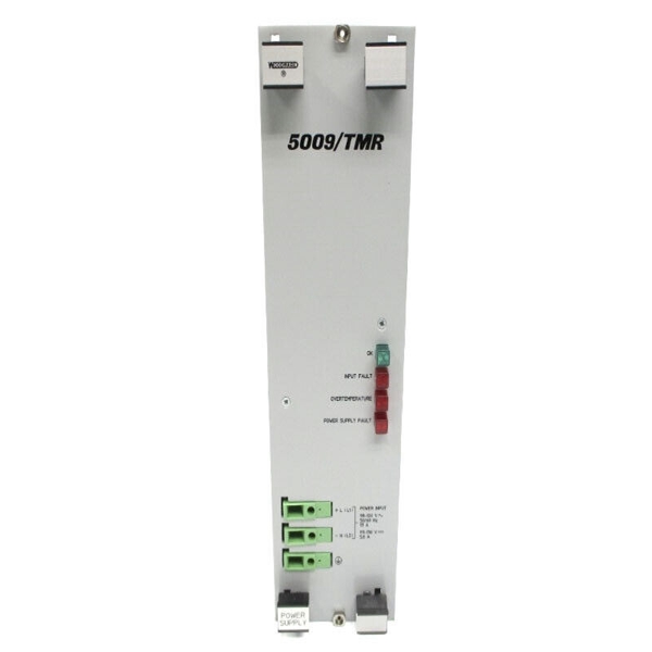
Brand: WoodWard
Model number:5460-840
Colour:new
Warranty: 12 months
Lead Time:3-day working day
Country of origin: USA Price: Please contact us
Product weight:0.85kg
Shipping Port: China
Payment: Bank of Chicago, Bank of Singapore
Express cooperation: fedex, DHL, UPS and your express account
Service: Professional Sales provides 24 hours /7 days online service
5460-840 WOODWARD
Be prepared to make an emergency shutdown when starting the engine, turbine, or other type of prime mover, to protect against runaway or overspeed with possible personal injury, loss of life, or property damage.

Speed and Phase Matching with an SPM-A Synchronizer
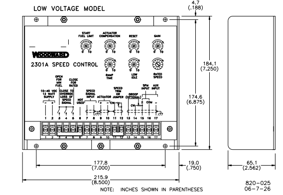
Connect the SPM-A (optional equipment) wires to terminals 15 (+/–) and 16
(com). Use shielded wire and connect the shield to the ground.
Auxiliary Input
Terminals 17 (–) and 15 (+) are used for auxiliary input from a load sensor. Use
of the load sensor and parallel lines allow the 2301A Speed Control to be used in
isochronous load-sharing circuits. If the load sensor is not used, droop must be
used to share load. (An exception is a multiple engine installation in which one
engine is operated isochronously and all other engines are operated in droop.)
Speed Sensor
Connect a speed-sensing device (a magnetic pickup (MPU) is normally used) to
terminals 8 and 7. No polarity is observed. Use shielded wire and connect the shield
only at the 2301A control. The shield must have continuity the entire distance to the
MPU. The shield is to be insulated from all other conductors and from the MPU.
Installation Check-Out Procedure
When the installation is completed perform the following check-out procedure
before beginning the start-up adjustments in Chapter 3.
1. Visual Inspection:
a. Check the linkage between the actuator and the prime mover for
looseness or binding. Refer to the appropriate actuator manual, and
Woodward manual 25070, Electronic Control Installation Guide, for
additional information on linkage.
The actuator lever should be near, but not at, the minimum position
when the fuel or steam rack is at the minimum position. This could
avoid a dangerous condition caused by an engine which will not shut
down.
b. Check for correct wiring according the plant wiring diagram.
c. Check for broken terminals and loose terminal screws. Make sure all
terminal lugs are carefully and correctly installed. (Incorrectly installed
crimp-on terminals can cause governor failure.)
d. Check the speed sensor (MPU) for visible damage. Check the
clearance between the gear and the sensor, and adjust if necessary.
See Woodward manual 82510, Magnetic Pickups and Proximity
Switches for Electronic Controls.
2. Check for Grounds.
With the power off, check for grounds by measuring the resistance between
each terminal and the grounding bolt located below terminal 9. Terminals 1
and 2 are power-input terminals. Either of these terminals may be grounded
in accordance with local codes or through other equipment powered from
the same supply. If either is grounded, a high resistance to ground will be
evident at terminals 1 through 5 on low voltage models and terminals 1
through 4 on high voltage models. grounds present on these terminals will
not normally affect operation, unless they interfere with the input power or
switching logic. Grounds on terminals 7 through 17, detected by readings
other than infinity, should be located and removed.

Woodward9907-005
WOODWARD9907-023
WOODWARD9907-1198
WOODWARD9907-166
WOODWARD9907-166M
WOODWARD9907-167
WOODWARD9907-205
WOODWARD9907-345
Woodward9907-345
WOODWARD9907-345 R
WOODWARD9907-838
WOODWARD9907-838
WOODWARDB210438
Woodwardcmw112
WOODWARDD210439
WOODWARDD210452
WOODWARDDB250-397
WOODWARDEC8551-094
WOODWARDEGB13C
WOODWARDEGB-13P
WOODWARDG8516-039
WoodwardWIP11-I1
WOODWARDWOODWARD 5503-215D
WOODWARDWoodward 21
WOODWARDWOODWARD 601-1008
WOODWARDWOODWARD 99
WOODWARDXD1G11
"WOODWARD "5441-407
WOODWARD5437-687
WOODWARD 5466-355
WOODWARD 5501-372
1
You are welcome to make an inquiry
E-mail:
free@fenoux.com
Tel.:
+86 133 7698 4225
Skype:
+86 133 7698 4225
WhatsApp:
+86 133 7698 4225