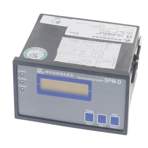
Brand: WoodWard
Model number:5448-906
Colour:new
Warranty: 12 months
Lead Time:3-day working day
Country of origin: USA Price: Please contact us
Product weight:0.85kg
Shipping Port: China
Payment: Bank of Chicago, Bank of Singapore
Express cooperation: fedex, DHL, UPS and your express account
Service: Professional Sales provides 24 hours /7 days online service
5448-906 WOODWARD
Be prepared to make an emergency shutdown when starting the engine, turbine, or other type of prime mover, to protect against runaway or overspeed with possible personal injury, loss of life, or property damage.

Speed Control
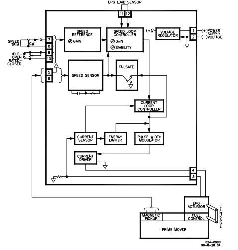
The basic speed control components and connections are shown in Figure 1-1.
There are no mechanical drive or hydraulic connections. All input power comes
from the battery. The speed control compares the actual speed with the desired
speed. It then calculates an error signal and drives the actuator in the increase or
decrease fuel direction to correct prime mover speed.
Figure 4-1 shows the Electrically Powered Governor in more detail. The speed
control is housed in a die-cast aluminum enclosure.
The EPG has two control loops. The speed loop ensures prime mover speed
remains constant. The current loop ensures proper drive to the actuator.
Speed Loop
The speed loop controller has two inputs: the desired speed (speed reference
signal) and the actual speed (the speed sensor signal). It compares the two and
calculates an error signal which includes dynamic response considerations. Gain
and stability adjustments tailor the governor’s response to the requirements of
the specific prime mover. Rated speed is set by the rated speed pot and, if
attached, a speed trim pot. The idle reference is controlled by an external idle
speed pot. Rated speed should be set before idle speed. Speed sensor output is
a voltage proportional to magnetic pickup frequency. The frequency range of the
magnetic pickup is set by an internal resistor. The specific frequency range of a
specific EPG Speed Control is indicated by the part number of the speed control.
Current Loop
The current loop error signal can be considered a command for the correct
amount of actuator current.
The actuator’s controller circuit compares actual current (from the current sensor
circuit) to the desired current level (from the speed loop controller) and generates
a current loop error signal. To make the current driver efficient, it is operated as a
switch. Actuator current is changed by changing the duty cycle. The pulse width
modulator converts the current loop error signal from a dc voltage to a switching
signal. For this reason measurements of speed control output [3 (+) and 4 (–)]
indicate only general conditions. Excessive currents are prevented from flowing
through the actuator coil by the energy limiter. It prevents the actuator from
overheating but allows enough current to keep the actuator at the maximum fuel
position.
The auxiliary input is jumpered except when a Load Sensor is added for
paralleled generator applications. There is a failsafe circuit which senses MPU
frequency and forces the pulse width modulator input to zero if the MPU
frequency or voltage are below acceptable limits, as they would be if an MPU
wire broke.

Woodward9907-005
WOODWARD9907-023
WOODWARD9907-1198
WOODWARD9907-166
WOODWARD9907-166M
WOODWARD9907-167
WOODWARD9907-205
WOODWARD9907-345
Woodward9907-345
WOODWARD9907-345 R
WOODWARD9907-838
WOODWARD9907-838
WOODWARDB210438
Woodwardcmw112
WOODWARDD210439
WOODWARDD210452
WOODWARDDB250-397
WOODWARDEC8551-094
WOODWARDEGB13C
WOODWARDEGB-13P
WOODWARDG8516-039
WoodwardWIP11-I1
WOODWARDWOODWARD 5503-215D
WOODWARDWoodward 21
WOODWARDWOODWARD 601-1008
WOODWARDWOODWARD 99
WOODWARDXD1G11
"WOODWARD "5441-407
WOODWARD5437-687
WOODWARD 5466-355
WOODWARD 5501-372
1
You are welcome to make an inquiry
E-mail:
free@fenoux.com
Tel.:
+86 133 7698 4225
Skype:
+86 133 7698 4225
WhatsApp:
+86 133 7698 4225