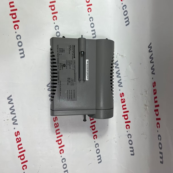
All Series C components feature an innovative design that supports enhanced heat management. This unique look
provides a significant reduction in overall size for the equivalent function.
Brand:HONEYWELL
Model number:R7247C-1001
Colour:new
Warranty: 12 months
Lead Time:3-day working day
Country of origin: USA
Price: Please contact us
Product weight:0.22kg
hipping Port: China
Payment: Bank of Chicago, Bank of Singapore
Express cooperation: fedex, DHL, UPS and your express account
Servce: Professional Sales provides 24 hours /7 days online service
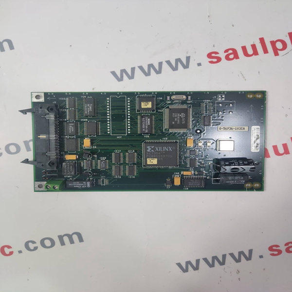
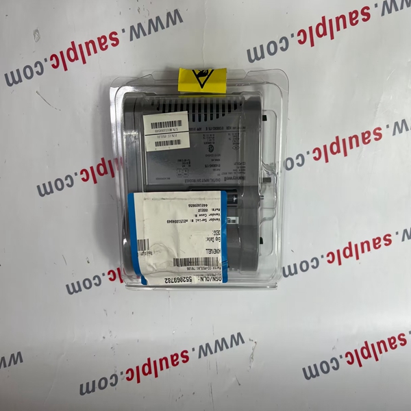
R7247C-1001 Honeywell Central control module Brand new


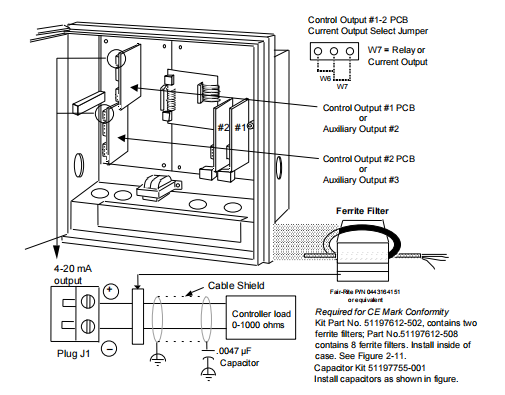
Position proportional control output wiring
You can wire control output 1 or 2 for position proportional output.
The prerequisites are:
· Model Number - Table 2 = 10 or 11
Refer to Figure 2-17 and follow the procedure in Table 2-16 to wire position proportional control output.
ATTENTION
Be sure to calibrate the position proportional control output so that the increase and decrease
relays operate properly with respect to the position of the external feedback slidewire. Refer to
Section 8 - Output Calibration in this manual.
Table 2-16 Position proportional control output wiring
Step Action
1 Open the recorder door. Loosen the captive screw in the chart plate and swing the plate out.
2 Locate connector J2 and J5 on the control output #1 printed circuit board (refer to Figure 2-17
for location) and remove the unwired plug from J2 and J5.
3 Locate jumper positions W2/W3 and W4/W5 below connector J5 on the printed circuit board.
Remove plug-in output #1 printed circuit board for better access to the jumpers. Be sure to tag
and remove all the plug connections to the printed circuit board before removing it. Position the
jumpers as shown in Figure 2-17 for desired relay contact action. Locate jumper position
W6/W7 on the bottom left portion of the board. Make sure position W6 is selected for position
proportioning, then reinstall the printed circuit board.
4 Run the feedback slidewire and motor drive wires through the desired knockouts.
5 For CE Mark conformity:
· install the ferrite filter as shown in Figure 2-11
· install the shield capacitors as shown in Figure 2-17.
6 Strip insulation from the end of each wire.
7 Loosen the screws in plug J2 terminals and position the plug as you would to plug it into J2.
8 Insert the wires from the motor’s feedback slidewire into the appropriate screw clamps as
shown (refer to Figure 2-17). Tighten the screws to secure the wires.
9 Loosen the screws in plug J5 terminals and position the plug as you would to plug it into J5.
10 Insert the wires for the motor into the appropriate screw clamps as shown (refer to Figure
2-17). Tighten the screws to secure the wires.
11 Install the wired plug into J2 and J5, as applicable.
12 Repeat steps 2 through 11 for Control Output #2 printed circuit board as applicable.
.

.
We have the same series of models in stock. If you don't find the model you need, please contact us and we will provide you with an official quotation!
HONEYWELL 30750338-005
HONEYWELL 51403393-100
HONEYWELL 30751044-4
HONEYWELL 30751044-009
HONEYWELL 30751044-7
HONEYWELL 51403393-200
HONEYWELL 4DP7APXIO211
HONEYWELL 30750318-2
HONEYWELL 30750318-3
HONEYWELL 51196882-100
HONEYWELL 51304095-100
HONEYWELL 51400997-200
HONEYWELL 51401088-100
HONEYWELL 51400926-100
HONEYWELL 51304537-100
HONEYWELL 51401583-200
HONEYWELL 51401583-100
HONEYWELL 51401996-100
HONEYWELL 51304421-100
HONEYWELL 51304441-175
HONEYWELL 51107137-117
HONEYWELL 51196654-100
HONEYWELL 51196653-100
HONEYWELL 51400712-100
HONEYWELL 51204166-175
HONEYWELL 51401201-100
HONEYWELL 51401577
You are welcome to make an inquiry
E-mail:
free@fenoux.com
Tel.:
+86 133 7698 4225
Skype:
+86 133 7698 4225
WhatsApp:
+86 133 7698 4225