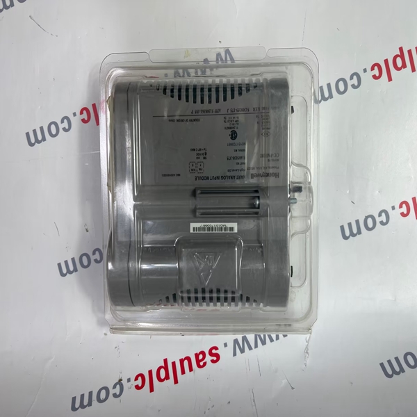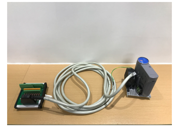
All Series C components feature an innovative design that supports enhanced heat management. This unique look
provides a significant reduction in overall size for the equivalent function.
Brand:HONEYWELL Model number:51404127-100
Colour:new Warranty: 12 months
Lead Time:3-day working day Country of origin: USA
Price: Please contact us Product weight:0.22kg
hipping Port: China
Payment: Bank of Chicago, Bank of Singapore
Express cooperation: fedex, DHL, UPS and your express account
Servce: Professional Sales provides 24 hours /7 days online service
51404127-100 Honeywell Input module Brand new

The green LED, DS1, on the IOTA adjacent to terminal block TB2 illuminates if either the Series C
system 24V internal system supply or an external user supplied power source is properly
connected to TB2. If this LED does not illuminate, check wiring to TB2, fuse F3, or the field wiring.
If TB2 is not used (no wires attached), then LED DS1 does not illuminate and this is normal.
6.6.3 Examples to illustrate sensor power connections through TB2
Example 1: Sensor powered from Series C System +24 V internal supply.
Connections made through TB1, FLDPWR(x)+ and COMMON(x)
The following figure displays a sample diagram where the sensor is powered from Series C system
+24 V internal supply and the power connections are made through TB1, FLDPWR(x)+ and
COMMON(x).
- 227 -
Chapter 6 - Series C PIM connectivity
Figure 6.9 Sensor powered from Series C System +24 V internal supply. Connections made through
TB1, FLDPWR(x), and COM(x)
For this type of connection, you need four wires. Two wires provide power to the sensor and the
other two wires connect the pulse output from the sensor to the PIM. This example shows the field
sensor connected to channel 1 but the procedure applies to the remaining channels.
The internal +24 Vdc supply, TB1, and TB2 are used to supply sensor power. This is accomplished
by connecting the corresponding channel’s FLDPWR1+ pin and COMMON1 pin to the positive and
negative power leads of the field sensor respectively. To complete the circuit, place the jumper wire
across the pins of the COM1 terminal block as illustrated in the above diagram so that so field
return is tied to COMMON1.
Install wires at TB2 as illustrated in the above diagram to feed all eight of the FLDPWR(x) to TB1.
There is no need to add individual wires from FLDPWR(x) to the +EXT 12V/24V connector at TB2 as
this is provided by internal copper tracks on the IOTA.
For clarity, the LED DS1 and other components are not shown in the above diagram. See also
figure PIM TB1 pin assignments.
Example 2: Sensor powered from Series C System +24 V internal supply.
Power connections directly made through TB2
The following figure displays a sample diagram where the sensor is powered from Series C system
+24 V internal supply and the power connects are directly made through TB2.
.

.
We have the same series of models in stock. If you don't find the model you need, please contact us and we will provide you with an official quotation!
HONEYWELL 30750338-005
HONEYWELL 51403393-100
HONEYWELL 30751044-4
HONEYWELL 30751044-009
HONEYWELL 30751044-7
HONEYWELL 51403393-200
HONEYWELL 4DP7APXIO211
HONEYWELL 30750318-2
HONEYWELL 30750318-3
HONEYWELL 51196882-100
HONEYWELL 51304095-100
HONEYWELL 51400997-200
HONEYWELL 51401088-100
HONEYWELL 51400926-100
HONEYWELL 51304537-100
HONEYWELL 51401583-200
HONEYWELL 51401583-100
HONEYWELL 51401996-100
HONEYWELL 51304421-100
HONEYWELL 51304441-175
HONEYWELL 51107137-117
HONEYWELL 51196654-100
HONEYWELL 51196653-100
HONEYWELL 51400712-100
HONEYWELL 51204166-175
HONEYWELL 51401201-100
HONEYWELL 51401577
You are welcome to make an inquiry
E-mail:
free@fenoux.com
Tel.:
+86 133 7698 4225
Skype:
+86 133 7698 4225
WhatsApp:
+86 133 7698 4225