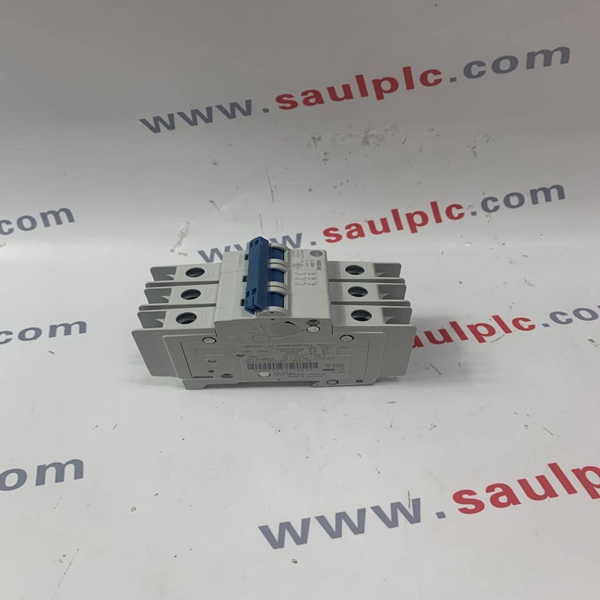
Brand: Allen-Bradley
Model number:1756-CNBR
Colour:new
Warranty: 12 months
Lead Time:3-day working day
Country of origin: USA
Price: Please contact us
Product weight:0.22kg
hipping Port: China
Payment: Bank of Chicago, Bank of Singapore
Express cooperation: fedex, DHL, UPS and your express account
Servzce: Professional Sales provides 24 hours /7 days online service
1756-CNBR Allen-Bradley Module spare parts spot

7. Verify that the module is installed in one of the following ways: Power the System • If the module is installed on a Compact GuardLogix 5380 controller or
Compact 5000 I/O EtherNet/IP adapter, the front of the Compact 5000 I/O After you install all Compact 5000 I/O modules, you can turn on MOD power and, if module is set back slightly from the front of the controller or adapter, used, SA power. respectively.
• If the module is installed on a Compact 5000 I/O module, the fronts of both For more information, see System Power Considerations on page 6.
modules are flush with each other.
Install the End Cap Remove the Module
1. Confirm that MOD power and all sources of SA power are turned off.
You must install an end cap on the last module in your system. IMPORTANT Before you remove power from the MOD power RTB 1. Align the end cap with the interlocking pieces on the module. and, if used, SA power RTB, consider the effect on
2. Push the end cap toward the DIN rail until it locks in place. your system.
When you remove MOD power and SA power from a
CompactLogix 5380 controller, Compact GuardLogix
5380 controller, or a Compact 5000 I/O EtherNet/IP
adapter, you shut down power to all Compact 5000
I/O modules. That is, all system-side and field-side
power is removed.
We strongly recommend that you take the
appropriate actions to help prevent unintended
consequences that can result from a system power
Interlocking Pieces shutdown before removing MOD power and
SA power.
2. If necessary, remove the end cap from the right side of the module.
3. If desired, complete the following steps to disconnect the serial cable from
the module:
End Cap a. Loosen the screws on both sides of the serial cable.
b. Pull the serial cable out of the module.
4. Press the DIN rail latch down until it clicks and let go of the latch.
5. Pull the module off the DIN rail.
Connect the Serial Cable

E-mail:
free@fenoux.com
Tel.:
+86 18030177860
Skype:
+86 18030177860
WhatsApp:
+86 18030177860