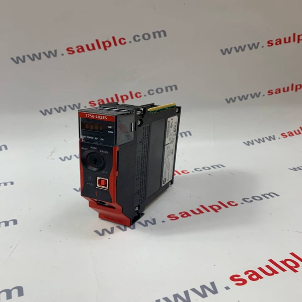
1734-AENT Allen- Bradley Card module spot
(The picture is in the folder.)
Brand:Allen-Bradley Model number:1734-AENT
Colour:new Warranty: 12 months
Lead Time:3-day working day Country of origin: USA
Price: Please contact us Product weight:0.75kg
Shipping Port: Xiamen, China
Payment: Bank of Chicago, Bank of Singapore
Express cooperation: fedex, DHL, UPS and your express account
Service: Professional Sales provides 24 hours /7 days online service
Product Dimensions: The table provides product dimensions. The 5.7-in. and 10.4-in. touch-screen terminals are shown for illustrative purposes. All other terminal sizes look similar. For information on proper mounting clamp installation, refer to the PanelView Plus 7 Standard Terminals User Manual, publication 2711P-UM007.

Mount a Module
This section explains how to mount 1786-RPA/B, 1786-RPCD,1786-RPFS, 1786-RPFM, 1786-RPFRL/B, and 1786-RPFRXL/B
modules.
.
Follow these steps to mount a module.
1.Position the module on the 35 x 7.5 mm (1.4 x 0.3 in.) DIN
rail (Allen-Bradley part number 199-DR1) at a 30°
angle.
2.Hook the lip on the rear of the module onto the top of the
DIN rail, and rotate the repeater module onto the rail.
3. Press the repeater module down onto the DIN rail until flush.
When the locking tab snaps into position, the repeater module is locked to the DIN rail.
If the repeater module does not snap into position, then use a screwdriver or similar device to move the locking tab
down as you press the repeater flush onto the DIN rail.
4. To lock the adapter in place, release the locking tab.
If necessary, push up on the locking tab to lock.
5. Once the repeater adapter is attached to the DIN rail, slide the repeater modules to the left to mate with the repeater
adapter.
6. To lock the repeater adapter and modules in place, attach the DIN rail locks to the left side of the repeater adapter and
the right side of the attached modules.
7. Repeat steps 1…6 for each of the two DIN rail locks.
8. Tighten the two screws on the DIN rail lock to a torque of 1.1 N•m (9…11 lb•in).
9. For the module you installed, continue with:
• Wire the 1786-RPA/B Repeater Adapter on page 3.
• Connect a 1786-RPCD Dual Copper Repeater Module on page 4.
• Connect a 1786-RPFS Fiber Module on page 4.
• Connect a 1786-RPFM, 1786-RPFRL/B, 1786-RPFRXL/B Fiber Module on page 4.
Wire the 1786-RPA/B Repeater Adapter
This section describes how to wire your module.
1. Make sure that you have obtained the following items before you begin to wire the module:
• Two lengths of 0.21…3.3 mm2
(24…12 AWG) wire
• Wire stripping tool
• Small, flathead screwdriver
2. Strip about 7 mm (0.28 in.) of insulation from the end of each wire.

2711P-T4W21D8S, 2711P-T4W22D8S, 2711P-T4W21D8S-B, 2711P-T4W22D8S-B, 2711P-T6C21D8S, 2711P-T6C22D8S, 2711P-T6C21D8S-B, 2711P-T6C22D8S-B, 2711P-T7C21D8S, 2711P-T7C22D8S, 2711P-T7C21D8S-B, 2711P-T7C22D8S-B, 2711P-T9W21D8S, 2711P-T9W22D8S, 2711P-T9W21D8S-B, 2711P-T9W22D8S-B, 2711P-T10C21D8S, 2711P-T10C22D8S, 2711P-T10C21D8S-B, 2711P-T10C22D8S-B, 2711P-T12W21D8S, 2711P-T12W22D8S, 2711P-T12W21D8S-B, 2711P-T12W22D8S-B, 2711P-T15C21D8S, 2711P-T15C22D8S, 2711P-T15C21D8S-B, 2711P-T15C22D8S-B
Contact person:Free
Email Address::free@fenoux.com
WhatApp: +86 133 7698 4225
We look forward to your inquiry and will get back to you as soon as possible.