Power utilization is the average power (kW) consumed by a servo axis. If Motion Analyzer
software was used to size the axis, the calculated axis power required can be used for the power
utilization value. If Motion Analyzer software was not used, you can use the continuous power
value (kW) for each module to determine mounting order.
1400-PM-ACC AB Motor Overload Protection
Brand:Allen-Bradley Model number:1400-PM-ACC
Colour:new Warranty: 12 months
Lead Time:3-day working day Country of origin: USA
Price: Please contact us Product weight:0.59kg
Shipping Port: China
Payment: Bank of Chicago, Bank of Singapore
Express cooperation: fedex, DHL, UPS and your express account
Service: Professional Sales provides 24 hours /7 days online service
1400-PM-ACC AB Input module Brand new

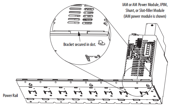
Mount the IAM/AM Power Modules
Follow these steps to mount the IAM, AM, IPIM, shunt, and slot-filler modules.
1. Remove the protective covers from the power rail connectors.
2. Determine the next available slot and module for mounting.
IMPORTANT The IAM power module must be positioned in the leftmost slot of the power rail. Position your
AM/IPIM modules, shunt module, and slot-filler modules to the right of the IAM module.
The shunt module must be installed to the right of the last AM/IPIM module. Only slot-filler
modules can be installed to the right of the shunt module.
Do not mount the shunt module on power rails with a follower IAM module. Common-bus
follower IAM modules disable the internal, rail mounted, and external shunt modules.
SHOCK HAZARD: To avoid personal injury due to electrical shock, place a 2094-PRF slot-filler
module in all empty slots on the power rail.
Any power rail connector without a module installed disables the drive system; however, control
power is still present.
TIP All modules mount to the power rail by using the same technique; however, only the IAM
module is shown.
IMPORTANT The IAM module must be positioned in the leftmost slot of the power rail. Position
your axis modules, shunt module, and slot-filler modules to the right of the IAM
module.
ATTENTION: To avoid damage to pins on the back of each IAM, AM, IPIM, shunt,
and slot-filler module, and to make sure that module pins mate properly with the
power rail, hang modules as shown in step 3 through step 6.
The power rail must be mounted vertically on the panel before hanging modules on
the power rail. Do not mount modules if the power rail is horizontal.

2711P-T4W21D8S, 2711P-T4W22D8S, 2711P-T4W21D8S-B, 2711P-T4W22D8S-B, 2711P-T6C21D8S, 2711P-T6C22D8S, 2711P-T6C21D8S-B, 2711P-T6C22D8S-B, 2711P-T7C21D8S, 2711P-T7C22D8S, 2711P-T7C21D8S-B, 2711P-T7C22D8S-B, 2711P-T9W21D8S, 2711P-T9W22D8S, 2711P-T9W21D8S-B, 2711P-T9W22D8S-B, 2711P-T10C21D8S, 2711P-T10C22D8S, 2711P-T10C21D8S-B, 2711P-T10C22D8S-B, 2711P-T12W21D8S, 2711P-T12W22D8S, 2711P-T12W21D8S-B, 2711P-T12W22D8S-B, 2711P-T15C21D8S, 2711P-T15C22D8S, 2711P-T15C21D8S-B, 2711P-T15C22D8S-B
Contact person:Free
Email Address::free@fenoux.com
WhatApp: +86 133 7698 4225
We look forward to your inquiry and will get back to you as soon as possible.